Figure 2C FLANGED HEATER Step 1. 33 Recent 3 Phase isolator Switch Wiring Diagram.
Phase angle fired zero voltage.

3 phase electric duct heater wiring diagram. Single Phase Three Phase TO CONVERT kW TO WATTS MULTIPL kW B 1000 Line Voltage Factor Line Voltage x 173 208 x 173 3598 220 x 173 3806 230 x 173 3979 240 x 173 4152 440 x 173 7612 460 x 173 7958 480 x 173 8304 550 x 173 9515 600 x 173 10380 Capacity Calculator Standard Air Conditions kW CFM x 108 x T 3414. Three Phase AC heater circuit where line voltage and current do not exceed thermostat rating. A rectangular duct with a length of at least 1 metre must be installed between fan and heater.
480V is the voltage between the 3 phases line to line. Duct strip and band heaters. In our wiring tutorial we have used 6 gauge wire for each hot wire.
Cut hole in side of duct 18 larger than heater body. Wiring arrangements for single and triple-phase are as shown in the wiring diagrams. Secure heater in place with sheet metal screws.
Standard Duct Heaters Open Coil 24 HUA Slip-in and HUP Flanged Heaters 24 KW Ratings 24 Frame Sizes 25 Sizes and Maximum KW Ratings 26 Detail Dimensions 26 Voltage and Phase 26 Control Circuit Options Special Features 26 Number of Heating Stages 27 Special Features 31 HUAHUP Sample Specification Custom Duct Heaters. Wiring diagram 3 phase heater. The heater must be installed in the correct position as shown by the arrows marked on the terminal box.
The heater should not be. Figure 1C SLIP-IN HEATER Step 1. 4 wire 3 Phase systems should use either A6Z 3CP or 3 single phase controls.
If instal-ling it before the fan make sure that the air flow temperature at the fan does not exceed the fans maximum temperature. Line current for either a single or three phase load is calculated as follows. The following diagrams show typical heater wiring schematics.
Let _L line and _Ph phase. For a delta connection line voltage Phase Voltage. For star or delta connections total power 3 phase power.
The SCR control can deliver electrical power to heaters in several ways. Of open coil and finned tubular duct heaters within minutes. Total Power Pt 3V_LI_Ph.
Leverage Watlows growing toolkit of calculators equations reference data and more to help design your thermal system. This may be accomplished by either an. A duct heater must be installed according to the installations instructions wiring diagram and labeling supplied with the heater.
Wiring Diagram for isolator Switch Save Rv Battery Disconnect Switch. The neutral can be omitted on the star arrangement whereas for the delta wiring the neutral is not suitable. Never operate a duct heater without airflow.
Constant resistance heaters only. You may use the appropriate cable wire and circuit breaker according to the heater rating. So 25A is spot on.
33 Recent 3 Phase isolator Switch Wiring Diagram. Secure heater flanges to duct flanges with sheet metal screws. I_Ph Pt3V_L I_Ph 15000W3208 2404A.
3 Phase Disconnect Switch Wiring Diagram Download - 33 Recent 3 Phase isolator Switch Wiring Diagram. 3-phase motor 400 120 kgm 3 Installation The heater must be installed downstream of the fan. Check the user manual and nameplate data printed on thermostat and heating elements.
Circuit does not have a positive off. Ohms Law Calculator 3-Phase Delta Wye Calculator. User manuals specification sheets CAD drawings and more.
Single or Three Phase AC heater circuit where line volt-. In this three phase wiring lighting small-appliance loads and receptacles are often connected between phase and neutral while larger equipments such as air conditioners and electric heaters are connected between two phases ie phase to phase. Listed below are some important items when installing an electric duct heater.
Wire and Breaker Size for Three Phase Electric Heaters. Single Phase AC circuits where line voltage and current do not exceed thermostat rating. The standard wiring for 3-phase electric heater batteries is star configuration with an incorporated neutral.
Insert heater until terminal box covers opening. The heater must always be interlocked with the fan. Sufficient clearance for convection cooling must be allowed for all heat- ers with built-in SCR Power Controllers.
With this software your local INDEECO representative becomes the source for certified prints wiring diagrams complete submittal information. A If you are looking for a modern day solution have a look at our AC Drive control panels that can also run 3 phase motors on single phase power includingv v connect power cord to terminals of control panel v1 white wire green wire to ground x2y2z2 u1w1 stator numbers located on the ends of the wires v overload red wire black wire orange wire to ground z1 w2 y1 v2 x1u2 wiring diagram three phase v. Provide at least 5 inches of free air Single Phase Line Current Three Phase Line Current.
Provide flanges on ends of duct matching heater flanges Step 2. Our heaters and controls range from the simplest standard duct heater to the most sophisticated custom designed comprehensive system.
Https Nailor Com Sites Nailor Com Files Downloads Nailor Electric Duct Heaters Catalog Pdf

Zy 1656 Watlow Heater Wiring Diagram Get Free Image About Wiring Diagram Download Diagram

Electric Heating Element Technical Reference Guide
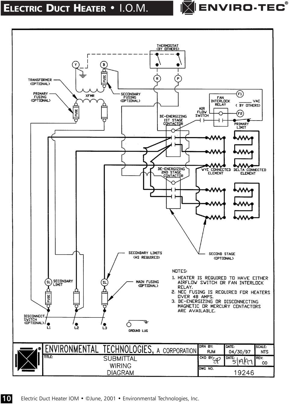
Electric Duct Heaters Pdf Free Download
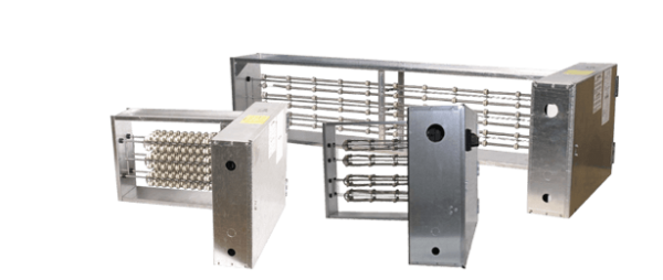
Tutco Hvac Duct Heater Solutions Product Category Introduction Page Tutco

Typical Wiring Diagrams Indeeco Flipbook By Fliphtml5

Electric Duct Heaters Pdf Free Download
Convectronics Electrical Data Connections And Wiring
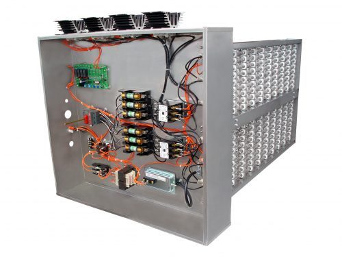
Custom Built Electric Duct Heaters Warren Hvac
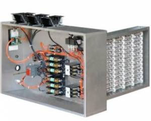
Custom Built Electric Duct Heaters Warren Hvac
220 Volt Electric Furnace Wiring



0 Comments