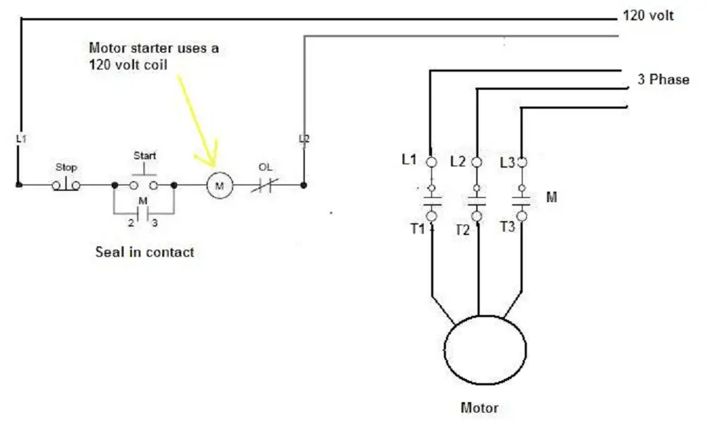
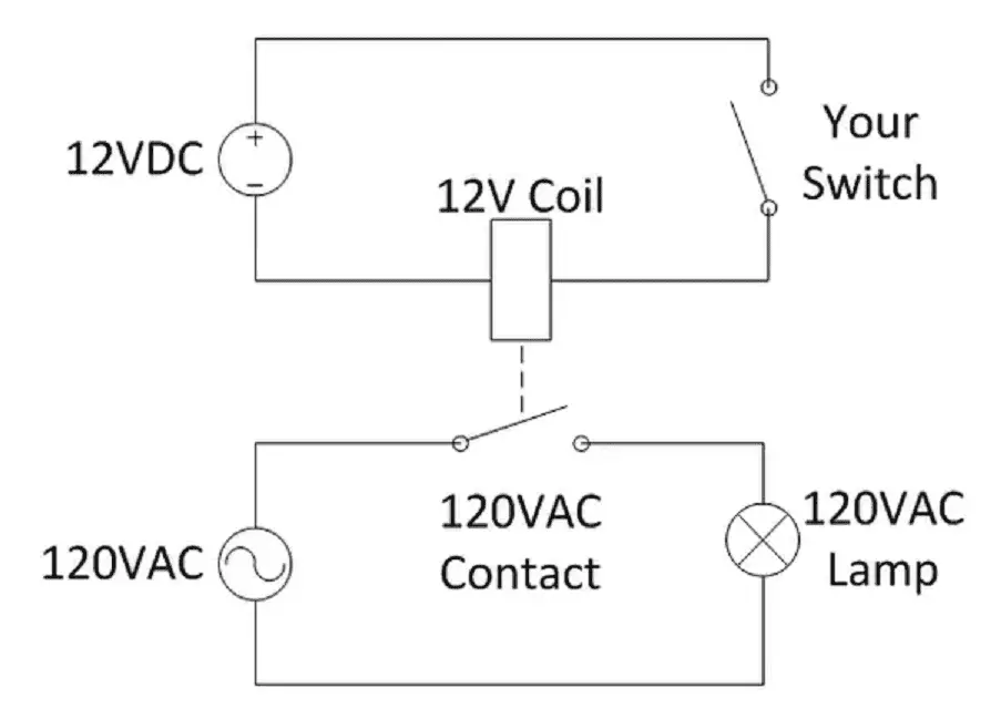
Potential free contacts are also sometimes called volt free or dry contacts and simply refer to relay contacts or switch or sensor contacts which havent been wetted with voltage by the machine or device in which they exist. That where you connect the wires going from its source 11 and the wire to the start 14.
The potential relay consists of a very high-resistance coil and a set of normally closed contacts.

Potential free contact relay wiring. NC Normally close contact. Fast Free Shipping on Orders Over 50. A potential free contact which is actually two contacts is for example the contacts of a relay that are controlled by some circuit as when they are either open or closed but are only physically mounted on say the PCB or in the same box but do not have any electrical connection to the voltagescurrents of the controller circuit.
The relay contacts of the KL2622 are potential-free and not connected to. It doesnt refer to some characteristic of the contacts themselves. Potential starting relays consist of a high resistance coil and a set of normally closed contacts.
12 Down Left To switch between flow rate totalizer. The term is used in controls where the Volt-Free Contact is used to indicate the status of a control or monitoring signal. The relay coil is wired between contacts 2 and 5 while the normally closed contacts are wired between contacts 1.
These contact shown in all Electrical drawings when circuit is in De-energised condition. A two terminal device NO or NC should be a path of any circuits current flow in previously such a device contact is called Potential free contact or in simple words an isolated contact is called potential free contact. Enter a valid email address.
The coil and contacts are encased in a small plastic housing see Figure 1. Relay has mostly two types of potential free contacts. The push button contact must be a good quality snap action switch to guarantee correct working at low voltages and reduce contact bounce effects.
NO Normally open contact. 2 Million Customers Choose Zoro. The contact should carry only our desired current or voltage.
Any ways the simple way the relay will have a Normally open contact 1114 or similar marked. Ad Compare and Save on Millions of Electronic Components Now. 800 AM - 800 PM ET UTC -5 Email.
This video explains the terminal arrangement of a potential relayhow to wire it up and how it works. A relay is an example of a volt free contact device as the operating coil is not connected to the contact s and will usually have a Common and a Normally open and a Normally closed set of contacts. Live chat is not available at this time.
When relay picked up NO contact gets closed. Same thing happened for NC contact. The coil is wired between terminals 2 and 5 with the contacts between terminals 1 and 2.
Volt free contacts or switching allow the user to switch a range of voltages from 24 up to 230 volts by applying their particular voltage to the Common terminal and connecting their appliance to. Volt-Free Contact is equivalent to Switch or Relay etc. Relay Box with Potential-Free Contacts Legrand AV.
A1 A2 you suplly with your reference potential to A2 and you take the to the coil through the switch and into A1 to start it. Try uploading a pic thats readale if zoomed and preferrably the correct way. A dry contact also known as a volt free contact or potential-free contact is defined as a contact in which powervoltage is not directly provided from the switch but is instead always being supplied by another source.
A potential free normally open push button can be connected. Please try again later or send us a message below. KL2622 2-channel relay output terminal potential-free make contact 1 The KL2622 output terminal has two relays each with a single contact and can be used to switch devices requiring mains power and operating at up to 230 V AC.
Like NO contact is open till the relay is not picked up or De-energised. Octopart Is The Preferred Search Engine for Electronic Parts. Why volt-free - well we also use transistor-type switches that operate slightly differently but generally the.
It should not mingle with other circuits auxiliary supplies.

Pin On Air Conditioning Repair Tips
Wet And Dry Contact Relay Explanation And Case Study Articleshook

3 Way Switch Wiring Diagram Of Electronics Pickups Pots Switches Jacks Capacitors Wire And 3 Way Switch Wiring Relay Diagram

Wiring Interposing Relays Npn Pnp Isolation Acc Automation

Pin On Air Conditioner Compressor

Resultado De Imagen Para Wj Electric Fan Wiring Diagram Camiones Toyota Toyota Camiones


0 Comments